


 Home /
Rechargeable Battery for Smart Devices: Custom Shape, PCM and Connector Engineering


Table of Contents
Smart devices rarely leave a simple rectangular battery cavity. PCBs, antennas, speakers, sensors and charging coils compete for the same internal volume. A Rechargeable Battery for Smart Devices should therefore be specified as part of the host system—not selected only by mAh.
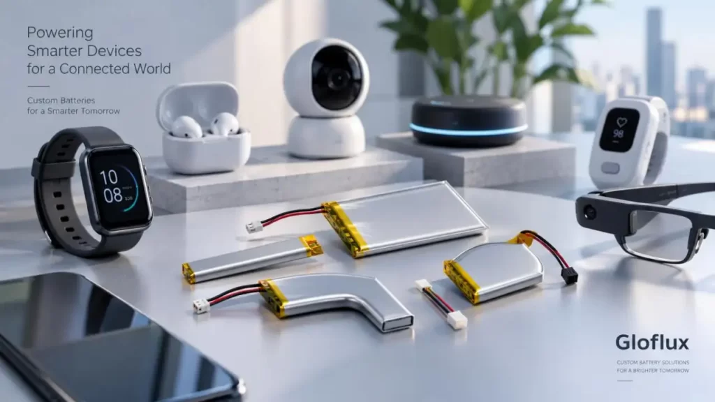
At Gloflux, the practical decision chain is mechanical fit → load profile → protection strategy → connector interface → installation → validation → production control. Gloflux supports custom LiPo dimensions, wiring, terminals, enclosures, PCM/BMS functions, NTC sensing and optional SMBus, I²C and CAN communication.
Start With the Real Battery Envelope
A custom-shaped LiPo can recover space that a standard rectangular cell wastes, but the whole cavity cannot become active electrode area. The design still needs pouch seals, separator overlap, tabs, PCM placement and assembly clearance.
For a Rechargeable Battery for Smart Devices, define the maximum L × W × T envelope, tab/cable exit, connector keep-out zone, mounting thickness, enclosure tolerance and expansion clearance.
Gloflux lists customizable LiPo length, width and thickness, with minimum thickness down to 3 mm for supported designs; feasibility still depends on capacity, current and pack structure.
| Battery Architecture | Best Use | Main Trade-Off |
| Standard rectangular cell | Regular cavities, lower development risk | Lower space utilization |
| Standard cell + custom PCM/wiring | Proven cell with device-specific interface | Fixed cell footprint |
| Custom-shaped LiPo | Thin or irregular smart devices | More engineering and dimensional control |
Custom geometry is justified when recovered volume or reduced product thickness creates measurable system value.
Match PCM Protection to Real Peak Loads
A Rechargeable Battery for Smart Devices may see short load peaks from Wi-Fi transmission, display wake-up, haptic motors, audio or processor boost. A battery can have enough capacity and still reset the device if the power path has excessive resistance.
Voltage drop ≈ Peak current × Total series resistance
Total resistance includes the cell, PCM MOSFETs, wires and connector contacts.
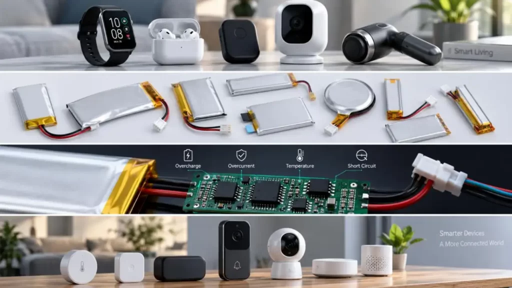
The PCM should coordinate:
• Overcharge and over-discharge protection
• Overcurrent and short-circuit protection
• Temperature monitoring where required
• Host low-voltage shutdown
If normal peak current approaches the PCM overcurrent threshold—or the protection delay is too short—normal operation can be mistaken for a fault. The device should also shut down normally before deep-discharge protection disconnects the pack.
PCM or Smart BMS?
| Requirement | Basic PCM | Smart BMS |
| OVP / UVP / OCP / short circuit | Yes | Yes |
| NTC input | Optional | Common |
| SOC estimation | Limited/external | Available |
| Communication | Usually none | I²C / SMBus / CAN |
| Best fit | Compact single-cell devices | Devices needing telemetry/control |
Gloflux can customize protection functions and communication interfaces instead of adding a smart BMS where it provides no system benefit.
Treat the Connector as Part of the Power Path
Connector selection for a Rechargeable Battery for Smart Devices affects both assembly and voltage stability.
A 2-pin interface may carry only positive and negative. A 3-pin design can add NTC sensing; 4-pin or multi-pin interfaces may add ID, fuel-gauge or communication signals.
Check current rating, contact resistance, wire gauge/length, polarity, retention, bend radius and mating-cycle requirements.
Since resistive heating rises with I²R, a small connector or thin wire can become the limiting element during current peaks.
Match Cell, Charger and Host PCB
Before freezing the Rechargeable Battery for Smart Devices, validate three system interfaces.
Charge-Voltage Platform
A 4.35 V or 4.4 V cell should not be treated as interchangeable with a 4.2 V system. Cell chemistry, charger IC and PCM thresholds must use the same voltage platform.
Peak-Current Path
Test the complete cell → PCM → wire → connector → PCB path under worst-case simultaneous loads, not only average current.
NTC and Cutoff Logic
Confirm NTC resistance, temperature thresholds and charger behavior. Coordinate host shutdown with PCM undervoltage protection so the product does not disconnect abruptly during normal use.
Design for Production Tolerance and Service
A prototype that fits does not guarantee production fit. Stack-up includes cell thickness, pouch seals, foam or adhesive, housing tolerance and cable routing.
For embedded packs, avoid rigid pouch compression, preserve expansion clearance and protect wires from sharp bends. Replaceable packs also need repeatable connector alignment, retention and service access.
Gloflux's development flow covers needs assessment, cell sourcing, engineering design, prototype testing and mass production, which helps keep mechanical and electrical decisions linked through the project.
Freeze the Configuration Before Compliance Testing
For portable lithium systems, IEC currently lists IEC 62133-2:2017+A1:2021. For transport, UNECE publishes the Manual of Tests and Criteria Rev.8 with Amendment 1 (2025), including changes to subsection 38.3.
Changing the cell, PCM or pack architecture after qualification should trigger an engineering review rather than assuming earlier reports automatically cover the new configuration.
What to Send Gloflux Before Custom Battery Development
For an actionable Rechargeable Battery for Smart Devices proposal, provide:
• 2D/3D available-space drawing
• Nominal/max charge voltage
• Average, continuous and peak current
• Required runtime
• Connector part number and pinout
• Wire length and exit direction
• NTC/communication requirements
• Mounting method
• Target markets and certification needs
Gloflux states that its manufacturing system uses more than 60 inspection procedures and has daily capacity of about 350,000 units.
Engineer the Battery as Part of the Device
A reliable Rechargeable Battery for Smart Devices is a system-matching problem: geometry determines usable volume, the PCM defines electrical limits, and the connector determines how effectively power reaches the PCB.
For smart wearables, IoT products, Bluetooth electronics and other compact devices, Gloflux can support custom LiPo and Li-ion development from dimensions and protection design through connector integration, prototyping and production. Visit Gloflux.com to evaluate the battery around the real device architecture rather than forcing the product around an off-the-shelf pack.
FAQs
Q1. Can Gloflux customize the shape of a Rechargeable Battery for Smart Devices?
Yes. Gloflux can support custom LiPo battery dimensions and pack structures for compact or irregular smart-device spaces. Final geometry depends on capacity, current requirements, pouch sealing, tab position and manufacturing feasibility.
Q2. Can Gloflux develop irregular-shaped LiPo batteries for smart devices?
Gloflux can evaluate irregular LiPo designs for applications where standard rectangular cells cannot use the available space efficiently. The design must still maintain sufficient electrode area, separator coverage and pouch-sealing margins.
Q3. Does Gloflux customize PCM protection for Rechargeable Battery for Smart Devices?
Yes. PCM functions can be configured according to the cell and host-device requirements, including overcharge, over-discharge, overcurrent and short-circuit protection.
Q4. Can Gloflux match PCM overcurrent protection to device peak current?
Yes. Engineers should provide continuous current, peak current and peak-duration data. Gloflux can use this information when evaluating the cell, protection circuit, MOSFETs, wires and connector power path.
Q5. Can Gloflux add NTC temperature sensing to a smart-device battery?
Yes. NTC sensing can be integrated when the device or charger requires battery-temperature monitoring. The NTC specification and connector pinout should be confirmed during development.
Talk to the Manufacturer
Resources & Insights
High Capacity Lithium Battery for Wearables: High-Voltage LiPo Cell Design
2026-10-19
Cylindrical Battery Packs for Laptops: 2S vs 3S vs 4S Battery Design
2026-10-19

Stage Lighting Battery Pack: Prevent Voltage Drop & LED Flicker
2026-10-19

Best Rechargeable Batteries for Smart Devices: Performance, Safety, and Selection Guide
2026-10-19


