


 Home /
Lithium Battery for Wireless Sensors: Pulse Current for LoRaWAN and NB-IoT


Table of Contents
- RF Transmission Is Often the Real Battery Stress Point
- LoRaWAN and NB-IoT Produce Different Load Profiles
- Capacity and Internal Resistance Must Be Evaluated Together
- Low Temperature Changes the Design Margin
- A Buffer Capacitor Helps Only When the Pulse Is Short Enough
- Direct Supply, Buck, Boost or Buck-Boost?
- Protection Circuit Settings Can Also Cause Unexpected Shutdown
- Validate the Worst Case, Not the Best Case
Wireless sensor nodes are usually described as low-power devices, but average current alone is a poor basis for battery selection. A sensor may remain in microamp-level sleep for most of the day and then demand a much higher current when LoRaWAN or NB-IoT transmission begins.
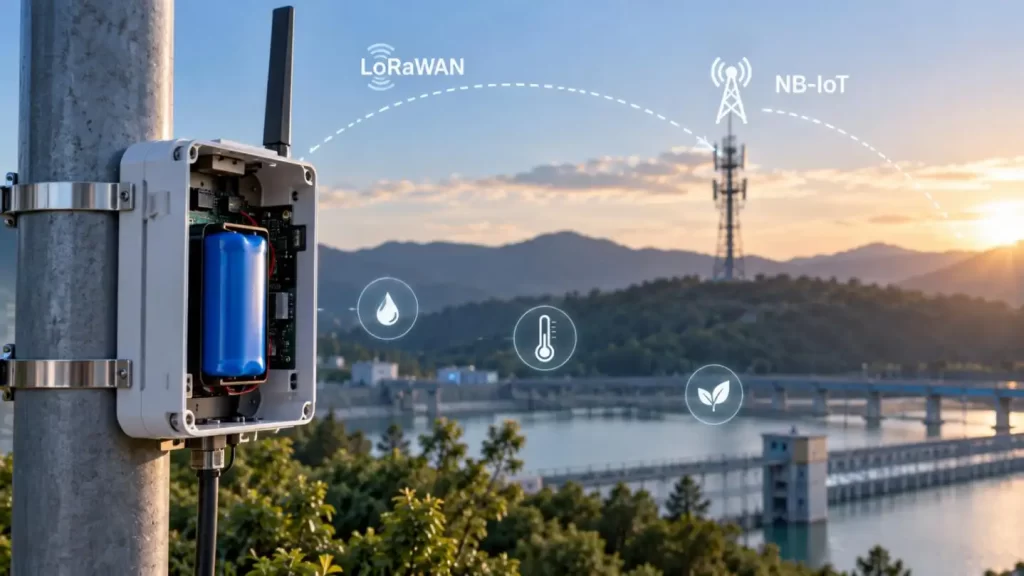
For this reason, selecting a Lithium Battery for Wireless Sensors requires engineers to evaluate not only capacity, but also pulse current, DC internal resistance, minimum operating voltage, SOC, temperature, protection-circuit resistance and the complete power path.
From Gloflux's battery engineering perspective, the critical question is simple:
Can the battery maintain sufficient terminal voltage during the worst RF transmission event—not only when new at 25°C, but also at low SOC and low temperature?
RF Transmission Is Often the Real Battery Stress Point
A wireless sensor may operate normally from a laboratory power supply yet reset when powered by the intended battery pack.
During RF transmission, the modem produces a transient current load. The resulting voltage drop can be approximated as:
ΔV ≈ Iₚᵤₗₛₑ × Rtotal
Where total resistance includes:
• Cell DC internal resistance
• PCM/BMS resistance
• Connector and wire resistance
• PCB trace resistance
• Contact resistance between components
The radio-side voltage becomes approximately:
Vload = VOC − ΔV
If this voltage falls below the modem or MCU brownout threshold, the system may reboot, lose packets or enter a repeated retry cycle.
This is why a high-capacity cell is not automatically the best Lithium Battery for Wireless Sensors.
LoRaWAN and NB-IoT Produce Different Load Profiles
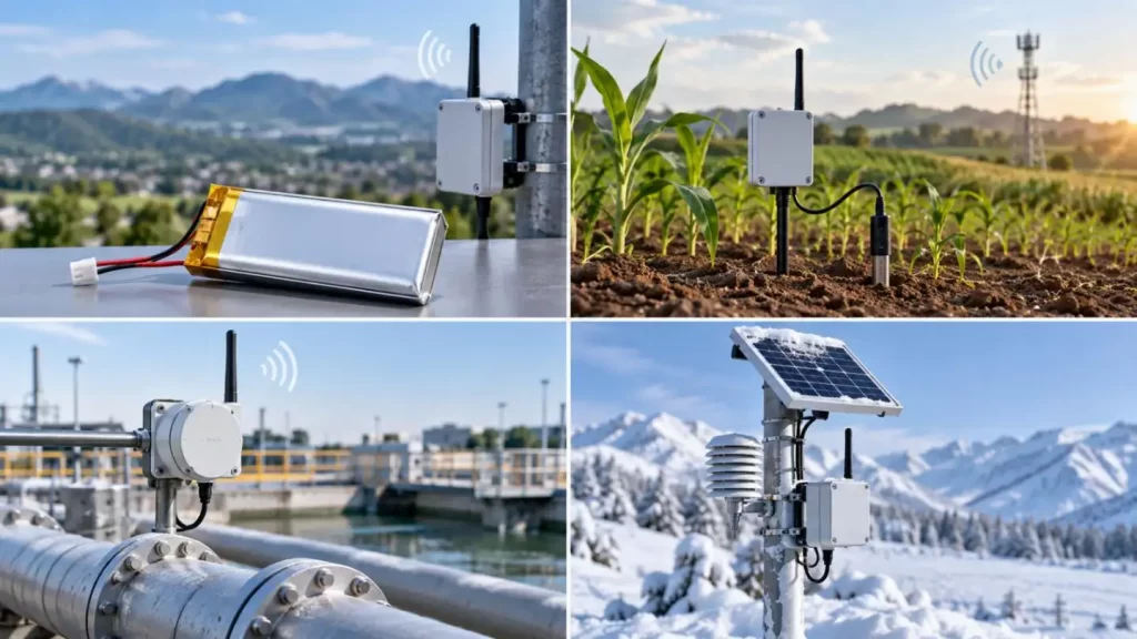
LoRaWAN and NB-IoT both support long-life sensor deployments, but they stress the battery differently.
| Engineering Factor | LoRaWAN | NB-IoT |
| Network | Gateway-based LPWAN | Cellular |
| Low-power operation | Long sleep between uplinks | PSM and eDRX |
| Main energy variables | TX power, data rate, spreading factor, airtime | Attach, TX, network response, retries |
| Typical battery challenge | Short RF bursts | Higher cellular burst and session energy |
| Poor coverage effect | Longer airtime or repeated uplinks | Longer connection and possible repetitions |
For LoRaWAN, spreading factor, transmit power and link quality influence airtime and energy consumed per successful packet.
For NB-IoT, PSM can reduce standby current substantially, but it does not remove the energy required for network attachment, transmission or retransmission.
Therefore, a Lithium Battery for Wireless Sensors should be selected using the actual modem current waveform rather than a generic "average current" figure.
Capacity and Internal Resistance Must Be Evaluated Together
Battery capacity determines how much total energy is available. Internal resistance determines how much voltage is lost when current suddenly increases.
These are different design parameters.
A suitable Lithium Battery for Wireless Sensors should satisfy both:
Energy Requirement
• Sleep current
• Sensor sampling current
• MCU processing time
• RF transmission energy
• Receive-window energy
• Self-discharge
• BMS/PCM quiescent current
• Regulator conversion losses
Pulse Requirement
• Maximum TX current
• Pulse duration
• Pulse repetition rate
• Minimum module voltage
• Cell DCIR
• End-of-life SOC
• Minimum operating temperature
A 3,000mAh cell with high resistance may produce more voltage sag than a lower-capacity cell designed for stronger pulse discharge.
Low Temperature Changes the Design Margin
Temperature is one of the most important variables in outdoor wireless sensors.
As temperature falls:
Electrochemical activity decreases → Cell resistance rises → Voltage sag increases
This can create a common field failure:
The sensor passes all tests at 25°C but resets during winter transmission.
A professional Lithium Battery for Wireless Sensors validation should therefore include cold-temperature RF testing rather than only low-temperature capacity testing.
Gloflux can configure wide-temperature lithium battery solutions around application requirements, including cell chemistry, capacity, voltage, discharge characteristics, PCM/BMS, connector and mechanical structure. Exact temperature limits should always be confirmed for the selected cell and finished pack.
A Buffer Capacitor Helps Only When the Pulse Is Short Enough
Adding a local capacitor near the radio can reduce short-duration voltage sag.
A first-order estimate is:
C ≈ I × Δt / ΔV
However, practical design must also consider:
• Capacitor ESR
• Leakage current
• Temperature derating
• DC-DC converter transient response
• PCB resistance
• Battery recharge time between pulses
A capacitor is useful when the RF burst is short and predictable. It is less effective if the battery itself cannot support sustained or repeated transmission loads.
For some wireless nodes, a battery-plus-capacitor architecture can outperform simply increasing battery capacity.
Direct Supply, Buck, Boost or Buck-Boost?
Battery selection cannot be separated from the regulator architecture.
| Power Architecture | Main Advantage | Main Risk |
| Direct battery | Low quiescent loss | Voltage varies with SOC |
| Buck | High efficiency | Requires input headroom |
| Boost | Maintains output at lower battery voltage | Raises battery-side peak current |
| Buck-boost | Wide usable input range | More complex transient behavior |
A boost converter is a good example of why system-level analysis matters. When battery voltage drops, input current can rise significantly to maintain output power.
The converter may therefore improve voltage regulation while increasing the pulse demand seen by the Lithium Battery for Wireless Sensors.
Protection Circuit Settings Can Also Cause Unexpected Shutdown
The battery may be capable of supporting the radio while the protection circuit is not.
Engineers should verify:
• PCM/BMS overcurrent threshold
• Overcurrent delay time
• MOSFET resistance
• Undervoltage cutoff
• Protection-board quiescent current
The overcurrent threshold must remain above legitimate RF peaks with appropriate tolerance, while still providing safe protection against abnormal loads.
At Gloflux, BMS/PCM selection can be integrated with cell selection and application current requirements instead of treating the protection board as a generic accessory.
Validate the Worst Case, Not the Best Case
Before mass production, Gloflux recommends validating a Lithium Battery for Wireless Sensors under realistic system conditions.
| Test Condition | What to Verify |
| Full SOC, 25°C | Baseline current waveform |
| Low SOC, 25°C | Remaining voltage margin |
| Low SOC, low temperature | Worst-case voltage sag |
| Weak network | Retries and longer radio activity |
| Maximum TX power | Peak current capability |
| Aged battery | End-of-life resistance margin |
Measurements should include:
• Minimum cell voltage
• Voltage at modem input
• Peak current
• Pulse duration
• DC-DC input/output voltage
• Reset or brownout events
Battery safety, wireless certification and transport compliance should also be evaluated separately. Requirements such as UN38.3, IEC 62133, FCC, ETSI or cellular certification depend on the battery design, end device and destination market.
A Better Way to Select a Lithium Battery for Wireless Sensors
The best Lithium Battery for Wireless Sensors is not simply the pack with the largest capacity. It is the pack that maintains stable voltage through the complete RF load profile at the lowest expected SOC, temperature and end-of-life condition.
Gloflux approaches wireless-sensor battery development as a system-matching process covering cell selection, PCM/BMS design, discharge performance, wiring, connectors, mechanical packaging, prototyping and production validation.
For LoRaWAN, NB-IoT and other wireless sensing applications, sharing the real current waveform and environmental limits with Gloflux early in development can reduce brownout risk and make battery-life estimates much closer to actual field performance.
FAQs
Q1. Can Gloflux customize a Lithium Battery for Wireless Sensors?
Yes. Gloflux can develop custom battery solutions based on voltage, capacity, pulse-current requirements, temperature range, dimensions, wiring, connectors and protection requirements.
Q2. Can Gloflux design batteries for LoRaWAN wireless sensors?
Yes. For LoRaWAN applications, Gloflux can evaluate the sensor's sleep current, TX pulse current, transmission interval, voltage range and environmental conditions before selecting a suitable battery configuration.
Q3. Can Gloflux provide a Lithium Battery for Wireless Sensors using NB-IoT?
Gloflux can develop battery packs for NB-IoT devices based on the actual modem load profile. Peak transmission current, network activity, low-SOC voltage and temperature should be evaluated during battery selection.
Q4. Why does Gloflux need pulse-current data from the wireless module?
Pulse-current data helps determine whether the cell and battery pack can maintain sufficient terminal voltage during RF transmission without excessive voltage sag or triggering protection circuitry.
Q5. Can Gloflux optimize battery internal resistance for wireless sensor applications?
Cell selection, pack structure, protection circuitry, wiring and connectors can all influence total power-path resistance. Gloflux can evaluate these factors according to the sensor's current profile.
Talk to the Manufacturer
Resources & Insights
High Capacity Lithium Battery for Wearables: High-Voltage LiPo Cell Design
2026-10-19
Cylindrical Battery Packs for Laptops: 2S vs 3S vs 4S Battery Design
2026-10-19
Stage Lighting Battery Pack: Prevent Voltage Drop & LED Flicker
2026-10-19
Best Rechargeable Batteries for Smart Devices: Performance, Safety, and Selection Guide
2026-10-19


